
 English
 русский
 Español
 عربى


Product Category
News Categories
Contact Us
Centrifugal Fan Sizing Guide: Steps to Match Airflow, Pressure & Efficiency
Content
Sizing a centrifugal fan looks straightforward until you are staring at a blank specification sheet. In our years of building centrifugal fans for HVAC, refrigeration, power electronics and clean-air equipment, we have seen the same few misunderstandings cause most selection problems: airflow versus pressure, blade geometry, and the point where the fan actually operates once installed. This guide walks through the sizing process the way we approach it in our own engineering and test lab, so you can avoid the shortcuts that lead to noise complaints, wasted energy, or a fan that simply under-delivers.
Start with the Operating Point
Before any catalogue page makes sense, you need two numbers: the airflow the system requires, and the static pressure it must overcome. Airflow is usually expressed in m³/h or CFM; static pressure in pascals (Pa) or inches of water gauge. The fan does not produce a fixed output. It follows a performance curve, and the actual operating point is where that curve intersects your system resistance curve.
If you tell us only "about 2,000 m³/h and not too noisy," we cannot give you a reliable selection. We need the actual system resistance: duct length and diameter, elbows, filters, heat exchangers, inlet and outlet conditions. A clean filter and a loaded filter create two different system curves, which means the operating point moves over time. The right fan has to keep working across that whole range, not just at the design condition.
This is also where people confuse power with performance. A larger motor does not automatically mean more airflow. The impeller geometry and speed determine where the fan lands on its curve; the motor only needs to be sized for that operating point. Start by defining reasonable worst-case and normal-case system curves, and you will have a solid basis for everything else.
Blade Shape Decides the Character of the Fan
The blade geometry of a centrifugal impeller sets the pressure behaviour, efficiency and operating flexibility. You will encounter three families in practice, and the choice between them is usually the first real decision in sizing.
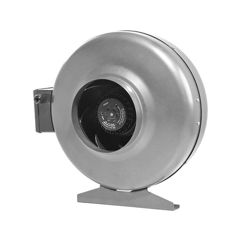
Forward curved blades have many shallow, closely spaced vanes and run at lower speeds. They deliver useful airflow at moderate static pressure from a compact impeller, which is why they appear so often in small blowers, HVAC fan coils and appliance applications. Their efficiency is more modest, and the pressure curve is steep, so the operating point can shift noticeably with small changes in system resistance. If your application is about moving large volumes of air at moderate pressure in a tight envelope, our industrial forward curved centrifugal blower is a practical starting point.
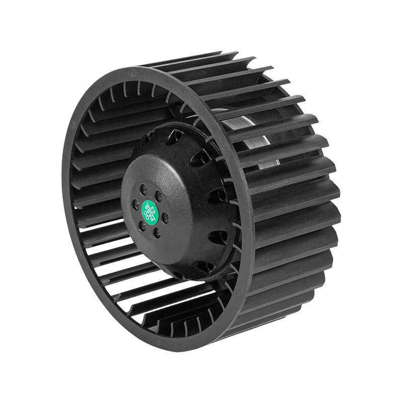 Industrial AC Forward Curved Centrifugal Blower for Compact HVACThis compact blower moves large air volumes at moderate pressure, ideal for roof fans and HVAC units where space is limited and system resistance varies.View Product →
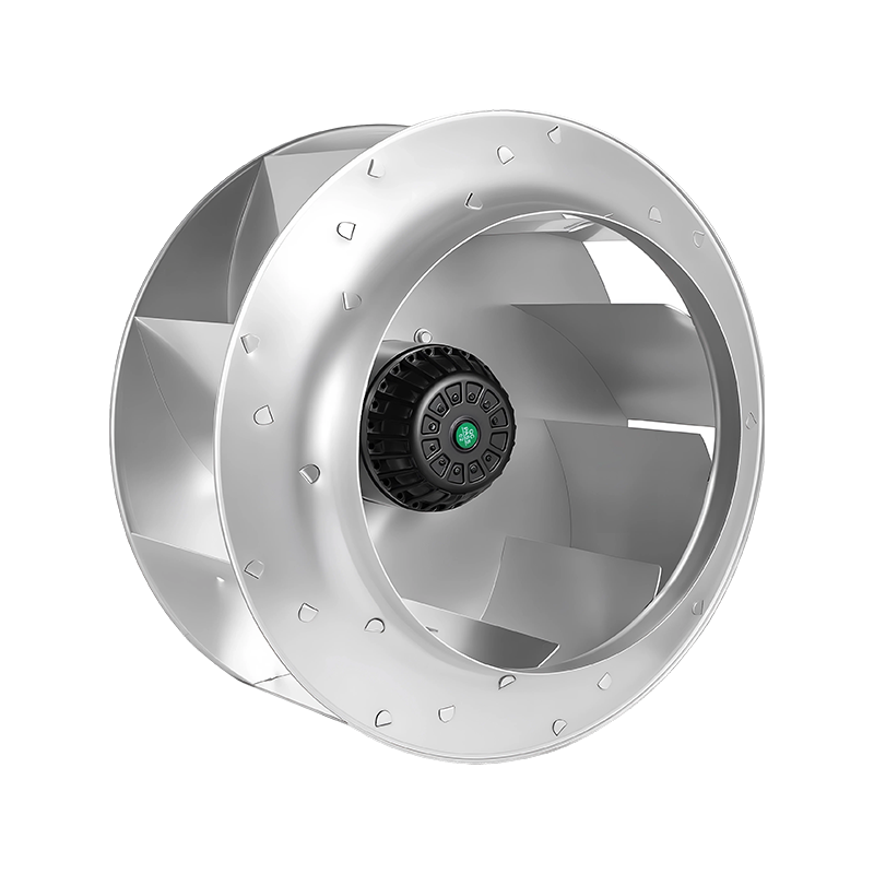
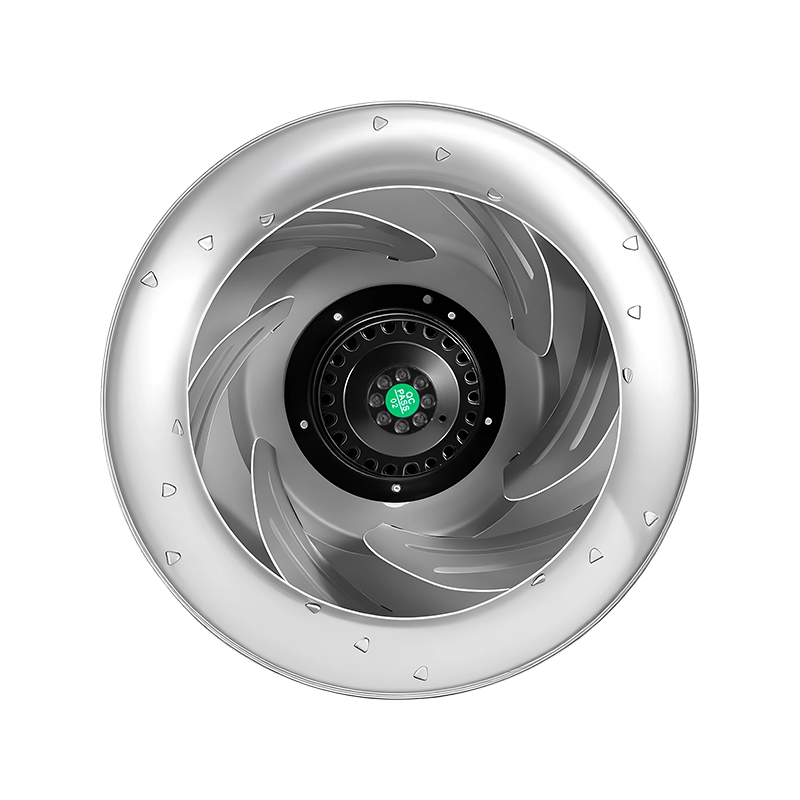
Backward curved blades, including airfoil profiles, are the workhorses of industrial ventilation. They generate higher pressure, run more efficiently and tolerate a much wider range of operating points without stalling or surging. If the system includes filters, long ducts, heat exchangers or any component whose resistance changes during operation, this is usually the safer choice. In our own range, these are the fans we specify for precision ventilating units and filtration equipment.
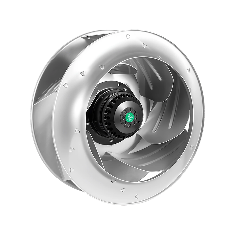 Low-Noise AC Backward Curved Centrifugal Fan for Precision VentilationDesigned for quiet, high-pressure duties in precision ventilation and filtration, this backward curved fan handles changing system resistance efficiently and reliably.View Product →
Radial blades form the third family. Their straight vanes handle particulate-laden and sticky air streams more easily, because there is less surface for material to catch on. The trade-off is higher noise and lower efficiency. They are essential in material handling and some process applications, but for clean-air systems a backward curved design is almost always the better starting point — you can compare both families in our centrifugal fan range.
Use Fan Laws Before You Commit to a Motor
The fan laws are the quickest sanity check in sizing. For a fixed fan geometry, airflow changes in direct proportion to speed, pressure changes with the square of speed, and power changes with the cube. If you increase speed from n₁ to n₂, the relationships look like this:
- Airflow: Q₂ = Q₁ × (n₂ / n₁)
- Static pressure: p₂ = p₁ × (n₂ / n₁)²
- Power: P₂ = P₁ × (n₂ / n₁)³
Those ratios explain why a seemingly small speed increase has a large effect on motor load. A 10% speed increase raises airflow by 10%, static pressure by roughly 21%, but shaft power by about 33%. Oversizing a motor "just to be safe" without recalculating the operating point can leave you with a motor that never runs near its efficient range — or worse, one that is actually too small once the system operating point shifts into a high-pressure region. This is the most common mistake we see in field retrofits.
Work Near the Best Efficiency Point
Every centrifugal fan has a best efficiency point, the region of its curve where the impeller converts input power into useful airflow and pressure most effectively. Running far from BEP does not only waste energy; it also raises noise and can excite vibration, which shortens bearing and belt life.
The system curve determines where you land. If the system is more restrictive than the fan selection assumed, the fan will deliver less air than expected and may operate in an unstable region. If the system resistance is lower than assumed, airflow rises and the motor can overload. That is why matching the fan curve to the real system curve matters more than any single catalogue number.
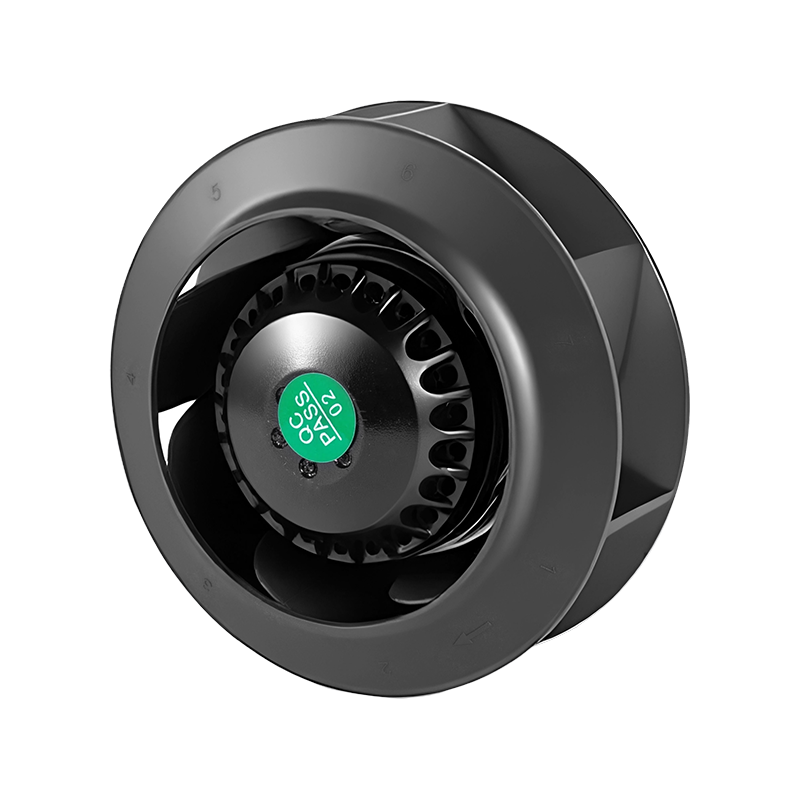
This is also where variable speed earns its keep. Instead of selecting a fixed-speed fan that sits near BEP at exactly one operating point, an EC centrifugal fan lets the controller adjust speed as filters load and demand changes. Many customers treat this as a direct AC upgrade for exactly that reason: it keeps the fan near its efficient region across a wide range of conditions rather than only at design point.
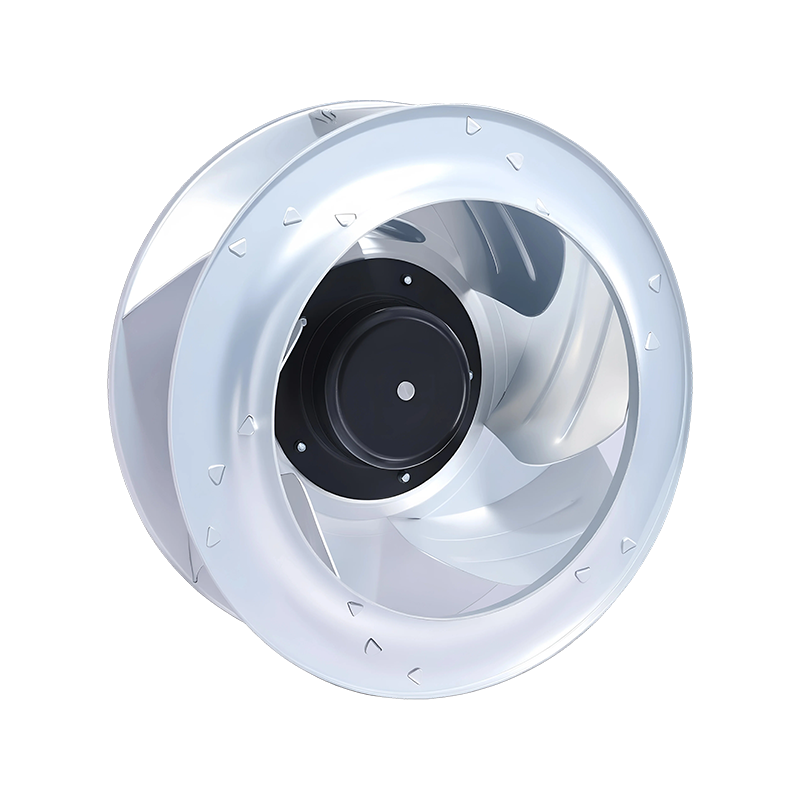 High-Efficiency EC Backward Curved Centrifugal Fan as Smart AC UpgradeThis EC fan offers variable-speed control to stay efficient across changing load conditions, making it a smart replacement for fixed-speed AC units in sustainable HVAC.View Product →
Density Changes Everything
Static pressure produced by a fan is tied to air density, and density changes with temperature and altitude. At higher elevations or elevated temperatures, the same fan at the same speed produces less static pressure because the air is thinner. If the system was designed at sea level and installed at 2,000 metres, the pressure requirement needs re-checking.
The correction is simple: calculate the actual density relative to standard air and apply it to the pressure requirement. We encounter this most often in industrial drying, heat recovery, data centres and high-altitude installations. Sizing software handles the calculation automatically, but only if someone remembers to enter the ambient condition in the first place.
What We Ask from Every Customer
To make a reliable centrifugal fan selection, we need a fairly short list of inputs. If you are preparing a request for quotation or trying to size a fan internally, gather these before opening any catalogue:
- Required airflow in m³/h or CFM
- Static pressure in Pa, mmH₂O or inches w.g.
- Air temperature, altitude and density
- Installation constraints: space, orientation, duct connection type
- Supply voltage and control preference: AC, EC or DC
- Special conditions: corrosive air, dust, moisture, noise limits, IP rating
The table below gives typical ranges we use as a starting point for common applications. Treat these as guidance only — the actual selection should always be verified against the manufacturer's performance curve.
| Application | Typical Airflow | Typical Static Pressure | Preferred Impeller |
|---|---|---|---|
| HVAC & precision ventilation | 500 – 20,000 m³/h | 200 – 1,200 Pa | Backward curved |
| FFU & air purification | 300 – 3,000 m³/h | 150 – 500 Pa | Backward curved |
| Refrigeration & cold chain | 500 – 10,000 m³/h | 300 – 800 Pa | Forward or backward curved |
| Industrial exhaust & process | 1,000 – 50,000 m³/h | 800 – 3,000 Pa | Radial or backward curved |
Sizing a centrifugal fan properly is not about finding the biggest, cheapest or most powerful model. It is about finding the point where the fan, the system and the motor work together across the operating range. Our engineers are happy to check your numbers and recommend a configuration. If you want to go deeper into airflow, pressure and drive types first, we have a centrifugal blower selection guide that covers the practical side of the process from a different angle.
NEXT:Types of Centrifugal Fans: A Practical Guide to Blades, Drives and Selection
Interested in cooperation or have questions?
-

sale3@beron-motor.com
-
 +86-15906637529
-
 Building 1 (12#), No. 619, Wangmei Road, Linping Street, Yuhang District, Hangzhou, China
 Wholesale Industrial Fan Manufacturers