
 English
  русский
  Español
  عربى
عربى 

Product Category
News Categories
Contact Us
Centrifugal Blower Selection Guide: Airflow, Pressure, and Drive Types
Content
- 1 Step 1: Fix the Duty Point Before You Look at Any Fan
- 2 Step 2: Read the Fan Curve Against the System Curve
- 3 Step 3: Match the Impeller Shape to the Pressure You Need
- 4 Step 4: Choose the Drive Type That Fits Your Supply
- 5 Step 5: Nail Down the Control Signal and Electrical Protection
- 6 Step 6: Check Noise, Temperature and Environment
- 7 Step 7: Match the Blower to the Application
- 8 Step 8: Get the Installation Details Right
- 9 A Practical Selection Checklist
Centrifugal blowers turn up in more places than most people expect: inside air handling units, behind filter banks in an FFU ceiling, on the exhaust side of a soldering line, and tucked into the cabinet of an air source heat pump. They move a lot of air from a small package and hold up far better than axial fans when the system pushes back with static pressure. The hard part is not the concept. It is choosing the one unit that sits at your duty point for years without howling, overheating, or leaving you short on airflow.
We build centrifugal fans and the motors that drive them, so this question fills most of our working hours. What follows is the order of thinking we use when a customer sends us an airflow figure, a pressure figure, and the space it has to fit into. If you want the fundamentals first, our explainer on what a centrifugal fan is and how it works is a comfortable starting point.
Step 1: Fix the Duty Point Before You Look at Any Fan
Every good selection starts with two numbers and the conditions behind them: the airflow you need, in m³/h or CFM, and the total static pressure the blower must overcome, in Pa or inches of water gauge. Together they define a single point on the fan curve, and everything else in the conversation depends on that point being right.
What trips people up is treating the airflow as free air. Density changes with altitude and temperature, so a blower specified at sea level behaves differently at 2,000 metres, or when it is pulling 60 °C air off a heat exchanger. Write down the real operating conditions rather than the nameplate ones.
- Required volumetric flow at the actual operating temperature
- Total static pressure across filters, coils, dampers, ductwork and discharge fittings
- Altitude and inlet air temperature, for density correction
- Duty cycle and expected service life
- Available electrical supply and control signal
- Noise limit, measured at a stated distance
- Physical envelope, mounting orientation and service access
A modest margin helps: around 10 to 15 percent on flow and 10 percent on pressure. Blanket margins do not. They push you toward an oversized impeller running well off its best efficiency point, drawing more power than necessary and usually making more noise.
Step 2: Read the Fan Curve Against the System Curve
A fan curve on its own tells you very little. Draw the system resistance curve over it, the line showing how much pressure your ductwork, filters and fittings need at each airflow, and the crossing point becomes your operating point. That is the number that matters.
Two habits separate a clean selection from a painful one. Stay off the steep left-hand end of the curve, where a small change in system pressure swings the flow widely; forward curved blowers are especially sensitive there. And respect the affinity laws when you think about speed: flow rises with speed, pressure with the square of speed, and shaft power with the cube. Turning a blower up by 20 percent asks for roughly 73 percent more power, which few motors forgive for long.
Remember too that the system curve moves. A clean filter and a loaded filter are two different systems, so check where the operating point lands at both ends of the maintenance cycle.
Step 3: Match the Impeller Shape to the Pressure You Need
Impeller geometry decides pressure, efficiency and noise long before drive electronics enter the picture. These four families cover the great majority of industrial and HVAC duty.
| Impeller type | Typical pressure | Efficiency | Best suited to | Watch out for |
|---|---|---|---|---|
| Forward curved | Low to medium | Moderate | Compact units, general ventilation | Sharp stall behaviour, lower efficiency |
| Backward curved | Medium to high | High | FFU and air purification, precision ventilating units | Needs more space, dislikes solids in the airstream |
| Radial | High | Lower | Dusty, sticky or hot process streams | Noise and power draw |
| Airfoil | Medium | Highest | Large volumes of clean air, energy-driven projects | Delicate blades, not for particulates |
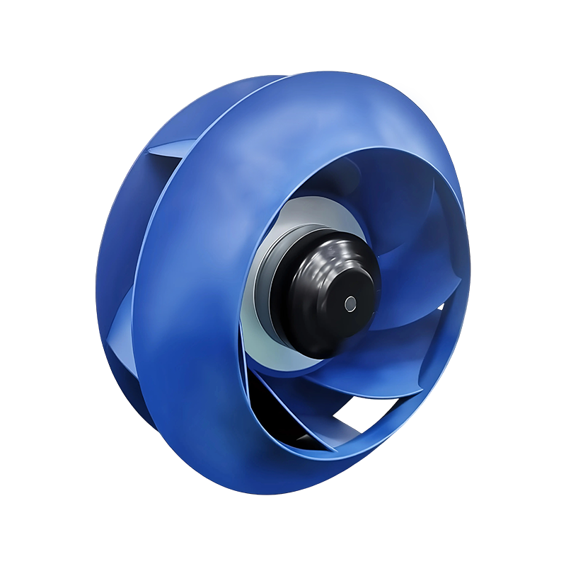
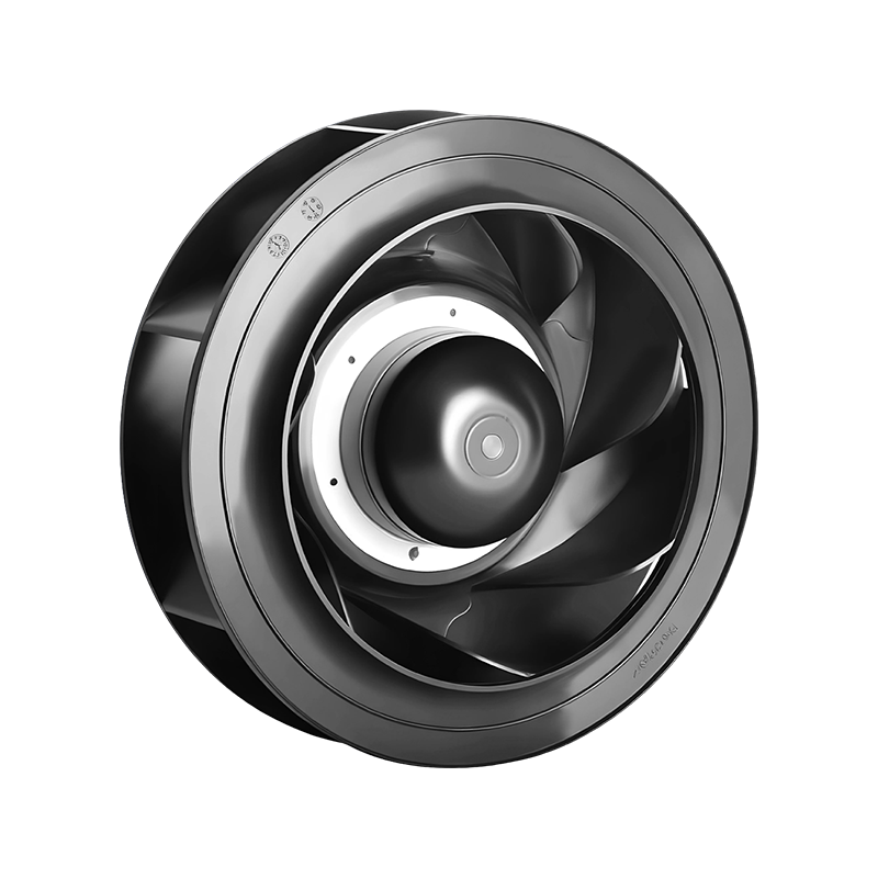
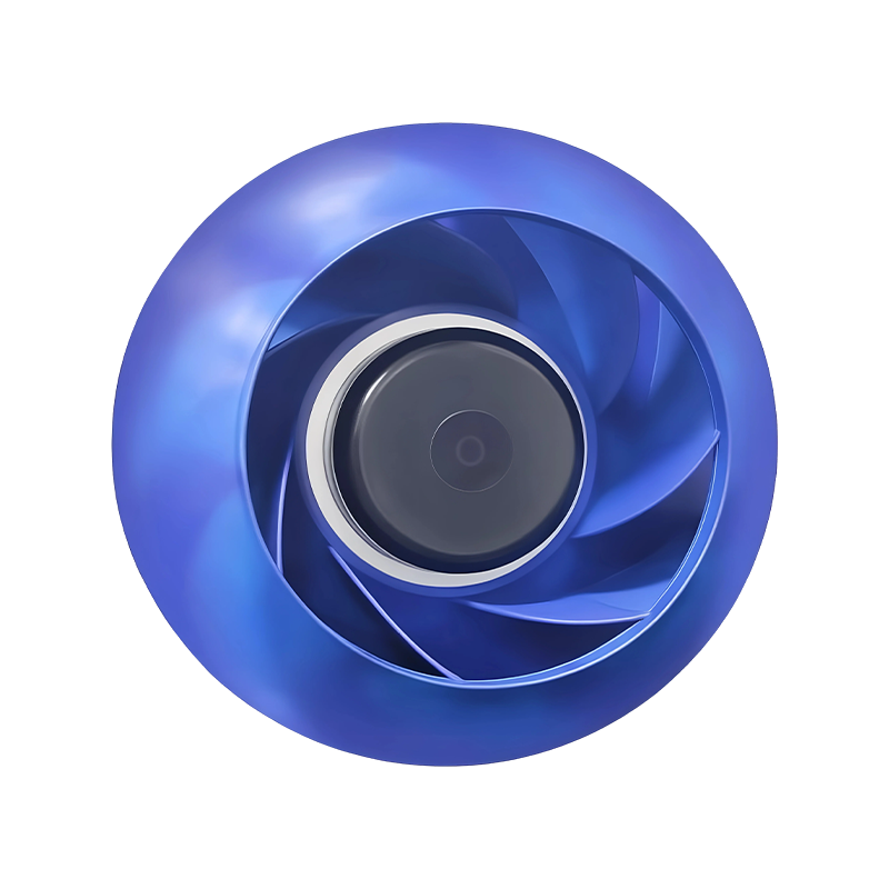
In practice, backward curved impellers carry most of the high-static work in filtering and purification, because they hold their efficiency while resistance climbs. For a concrete example, consider the high-pressure backward curved AC centrifugal fan below, built for air purification and FFU duty where pressure and noise both have to stay in check.
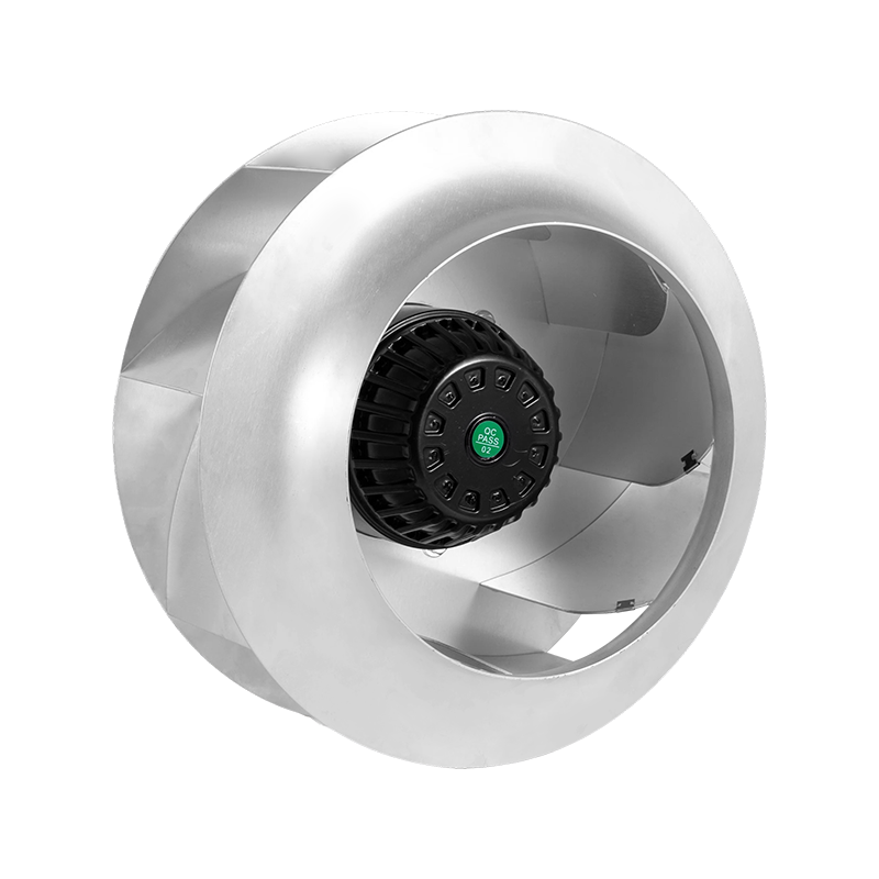 High-Pressure AC Backward Curved Centrifugal Fan for Air Purification and FFUA high-pressure backward-curved AC centrifugal fan for air purification and FFU systems, offered in 315-frame models with CCC/CE approvals.View Product →
Step 4: Choose the Drive Type That Fits Your Supply
Once the impeller is settled, the motor and its control determine how the blower behaves in the real world. AC induction motors are simple and inexpensive, running at a fixed speed from the mains. EC blowers carry their electronics on board and accept a 0-10V signal directly, which is why they have become a common drop-in upgrade for older AC units. DC blowers run from 12V, 24V or 48V supplies and suit battery, telecom and mobile equipment where a mains feed is not available.
| Drive | Speed control | Typical supply | Best fit |
|---|---|---|---|
| AC induction | Fixed speed, or external voltage controller | 110V / 220V / 380V | Simple ventilation, cost-sensitive builds |
| EC brushless with integrated electronics | 0-10V or PWM stepless regulation | Mains AC input | Energy-driven HVAC, AC replacement projects |
| DC brushless | PWM or 0-10V, wide turndown | 12V / 24V / 48V | Telecom, refrigeration, off-grid and mobile equipment |
| BLDC motor without impeller | External controller | 12V / 24V / 48V | OEM designs supplying the impeller separately |
Energy use usually decides the matter. A well-matched EC or BLDC unit holds high efficiency across a wide speed range, which counts in systems that run continuously and in installations where airflow has to be trimmed after commissioning.
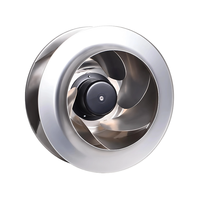
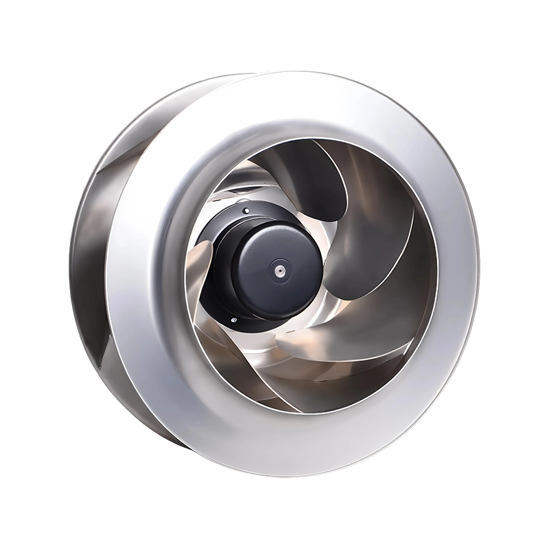 EC Centrifugal Blower for AC Upgrades and Energy-Saving RetrofitsA customizable EC centrifugal blower with integrated 0-10V/PWM control, positioned for AC-to-EC retrofits, AHU/PAU ventilation, and green-building compliance.View Product →
Step 5: Nail Down the Control Signal and Electrical Protection
Control details are easy to postpone and expensive to fix later. Decide early whether the blower will be set once and left alone, adjusted by a building management system, or modulated continuously against a temperature or pressure sensor. An EC centrifugal blower with an integrated 0-10V input removes the need for external speed controllers, simplifying the panel and cutting wiring time. Where a PWM signal is preferred, or the supply is a 24V or 48V DC bus, the same logic applies: match the control method to the equipment you already have.
Protection is the other half of this step. Thermal overload protection, overvoltage and reverse polarity protection on DC units, and class F insulation on the winding all matter in industrial settings where the supply is not always clean. For equipment running unattended, choose a blower that fails safely rather than one that simply stops without warning.
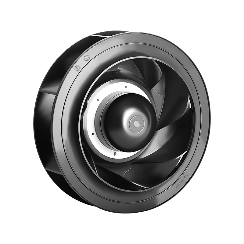 High-Static-Pressure DC Centrifugal Blower with 0-10V/PWM Speed RegulationA compact industrial DC centrifugal blower with backward-curved impeller and 0-10V/PWM control, intended for medical, 3D-printing, and electronics cooling applications.View Product →
Step 6: Check Noise, Temperature and Environment
Noise is one of the first things an end user notices and one of the last things engineers check. A published sound figure only means something when you know the distance and the operating point it was measured at, so ask for data at your duty point rather than at free delivery. Reducing speed is usually the cheapest way to quieten a blower, since sound pressure falls noticeably with every small drop in impeller tip speed. Bearing quality and blade pass tones deserve attention too, especially in occupied spaces.
Temperature and environment narrow the field further. If the motor sits inside the airstream, air temperature becomes a motor cooling question as well as a process question. Dust, moisture and washdown demand a look at ingress protection and at whether the impeller can tolerate particles at all.
Step 7: Match the Blower to the Application
A duty point never exists in isolation; it comes from an application. In air conditioning and ventilation, the priorities are usually quiet operation, stable airflow against varying filter load, and a tidy fit inside the unit. In refrigeration and cold chain equipment, low temperature starting and reliable lubrication matter more than raw efficiency. FFU and air purification systems want high static pressure with low noise, because both the filter and the diffusion media cost pressure. IT and communication cabinets, power electronics and household appliances each add their own constraints on space, supply voltage and service life.
Write those constraints down next to the duty point. A blower that is perfect for a rooftop ventilation unit is rarely the right answer inside a telecom cabinet, even when the airflow figures look similar.
Step 8: Get the Installation Details Right
Even a well-selected blower can underperform once it is bolted into the machine. Keep the inlet clear of obstructions, because a blower starved at the inlet loses flow and gains noise. Use flexible connectors between the blower and rigid ductwork so vibration does not travel into the structure, and confirm the discharge direction and rotation before the wiring is finished.
Throttling is another common surprise. Dampers on the inlet side shift the operating point in ways that are harder to predict than discharge-side control, so if airflow must be trimmed, use speed control or a discharge damper. If the equipment runs continuously, plan filter changes and bearing checks into the maintenance schedule from day one.
A Practical Selection Checklist
- Confirm airflow and static pressure at real operating conditions.
- Correct for altitude, temperature and air density.
- Plot the system curve and check the operating point with clean and loaded filters.
- Choose an impeller shape that matches the pressure and the air quality.
- Pick AC, EC or DC drive based on supply, control and energy targets.
- Confirm the blower accepts your control signal without extra hardware.
- Check protection features, insulation class and ingress protection.
- Verify noise data at your duty point, not at free delivery.
- Review mounting, inlet clearance and service access.
- Ask for a tested curve, and a sample where the project is critical.
Selection is really a conversation between your system and the blower, and the earlier it happens the fewer surprises you meet at commissioning. Share the airflow, the pressure, the supply and the space you have, and most of the remaining choices fall into place quickly. We keep wind tunnel, noise and motor performance labs on site for exactly that reason, so duty points get verified rather than estimated, and we are glad to review a specification with you long before anyone talks about an order.
NEXT:Types of Centrifugal Blowers: Forward-Curved, Backward-Curved & Radial
Interested in cooperation or have questions?
-

sale3@beron-motor.com
-
 +86-15906637529
 -
 Building 1 (12#), No. 619, Wangmei Road, Linping Street, Yuhang District, Hangzhou, China
 Wholesale Industrial Fan Manufacturers