
 English
  русский
  Español
  عربى
عربى 

Product Category
News Categories
Contact Us
What Is a Centrifugal Fan and How Does It Work in Industrial Air Systems
Content
- 1 Centrifugal Fan Engineering: Structure, Selection, Balancing and Field Performance
- 2 Key Differences Between a Centrifugal Fan and a Normal Fan
- 3 How Does a Centrifugal Fan Work?
- 4 What Is Another Name for a Centrifugal Fan?
- 5 What Are the Different Types of Centrifugal Fans?
- 6 Which Type of Centrifugal Fan Is the Most Efficient?
- 7 What Are the Advantages of Centrifugal Fans?
- 8 How to Select a Centrifugal Fan
- 9 What Is the Correct Orientation for a Centrifugal Fan?
- 10 How to Balance a Centrifugal Fan
- 11 What Is the Lifespan of a Centrifugal Fan?
- 12 Are Centrifugal Fans Better?
- 13 What Are the Common Problems with Centrifugal Fans?
- 14 Where Are Centrifugal Fans Used?
- 14.0.1 Boiler and Furnace Duty
- 14.0.2 Dust Collection
- 14.0.3 HVAC and Cleanrooms
- 14.0.4 Pneumatic Conveying
- 14.0.5 Tunnel and Mine Ventilation
- 14.0.6 Cooling Towers
- 14.0.7 Food and Agricultural Processing
- 14.0.8 Marine and Offshore
- 14.0.9 Data Centre Cooling
- 14.0.10 Chemical and Pharmaceutical
- 14.0.11 Wastewater Treatment
- 14.0.12 Paint and Coating Plants
- 15 Operating Cost and Energy Considerations
- 16 Installation and Commissioning Checks
- 17 Materials and Construction Choices
- 18 Performance Verification After Installation
- 19 Maintenance Schedule Framework
- 20 Engineering Support and Documentation
Centrifugal Fan Engineering: Structure, Selection, Balancing and Field Performance
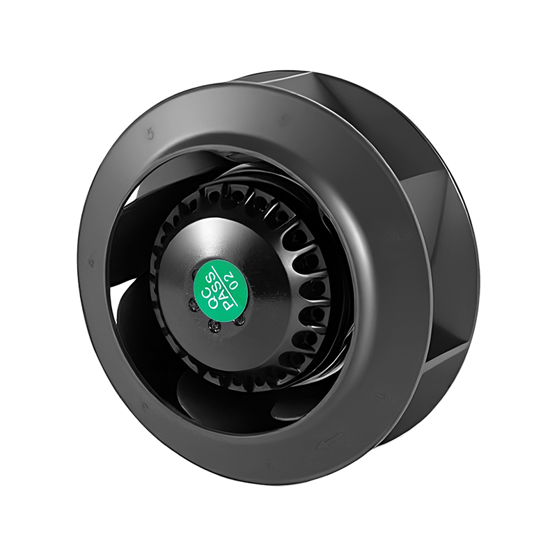
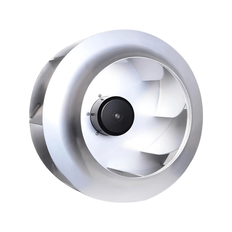
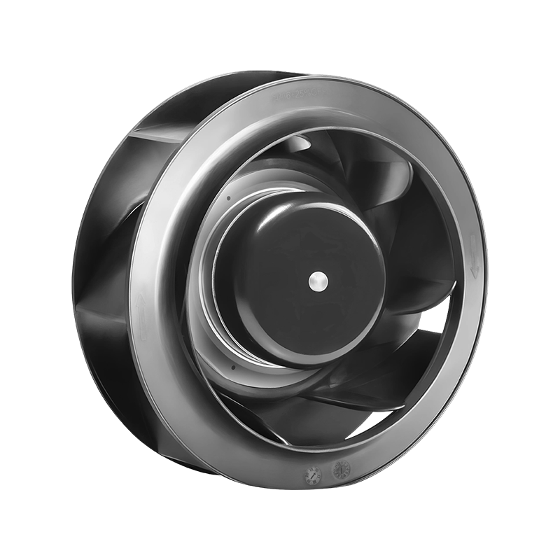
A centrifugal fan is a rotating air-moving machine that converts mechanical energy from a motor into aerodynamic energy inside a spinning impeller. Air enters along the axis of the shaft, is captured between the blades, gains velocity as the impeller turns, and is then thrown outward at roughly ninety degrees to the inlet. That sharp change of direction is what separates this machine from every other air handler on the market, and it explains almost every performance characteristic that follows — the high static pressure, the compact discharge, the tolerance for long duct runs, and the characteristic noise signature.
Understanding the centrifugal fan on a technical level matters because the machine sits inside so many critical systems. It moves combustion air into boilers, pulls dust-laden gas out of grinding circuits, supplies conditioned air to hospital wards, drives pneumatic conveying lines for cement and grain, ventilates underground tunnels, cools data centre halls, and dries agricultural products in bulk. Choosing the wrong impeller style, the wrong rotation, or the wrong drive arrangement does not simply reduce efficiency — it can stall the process, overload the motor, or destroy the bearing assembly within weeks.
Airflow Pattern
Axial inlet, radial outlet. The gas path turns approximately ninety degrees between the inlet cone and the discharge flange, which is the defining geometric feature of the design.
Pressure Capability
Single-stage units commonly deliver 500 to 15,000 Pa of total pressure. Multi-stage arrangements push considerably higher when a process demands it.
Volume Range
From a few hundred cubic metres per hour on small laboratory units to well over one million cubic metres per hour on large induced draught machines.
Construction Options
Carbon steel, stainless steel, FRP, rubber-lined, abrasion-resistant plate, and high-temperature alloy configurations are all available depending on the gas stream.
Key Differences Between a Centrifugal Fan and a Normal Fan
The term "normal fan" in everyday conversation usually refers to a propeller fan or an axial fan — the kind of open-frame unit that sits in a wall opening, a window, or a short duct and simply pushes a large volume of air through a low-resistance path. Comparing a centrifugal fan with a propeller fan is therefore a comparison between two fundamentally different aerodynamic strategies, not between two quality levels of the same product.
A propeller fan moves air parallel to the shaft. The blades are essentially rotating wings that accelerate the gas along the axis. Because the gas never changes direction, the pressure gain is modest — typically under 500 Pa — and any downstream resistance chokes the flow quickly. A centrifugal fan moves air perpendicular to the shaft. The impeller acts as a rotating compressor stage, and the scroll-shaped casing converts velocity into pressure. This is why a centrifugal fan can push air through a hundred metres of ducting while a propeller fan of the same motor rating cannot manage ten.
Performance Parameter Comparison
| Parameter | Centrifugal Fan | Propeller / Normal Fan |
| Direction of airflow | Axial in, radial out (90° turn) | Axial in, axial out (straight through) |
| Static pressure range | 500 – 15,000 Pa single stage | 30 – 500 Pa |
| Volume flow at high resistance | Remains stable as resistance rises | Falls sharply as resistance rises |
| Typical impeller tip speed | 25 – 90 m/s | 10 – 40 m/s |
| Duct compatibility | Long runs, bends, filters, scrubbers | Open air, short sleeves, wall mounting |
| Noise character | Broadband plus blade-pass tone | Predominantly broadband airflow noise |
| Footprint for equal duty | Larger, scroll housing required | Compact, ring or plate mounted |
| Particle tolerance | High with correct impeller and liner | Low, blades erode and foul |
| Speed control benefit | Very high, cube-law power saving | Moderate, limited by low pressure |
| Reversible operation | Possible with symmetric impeller design | Commonly reversible |
The practical consequence of these differences shows up in system design. When an engineer specifies a propeller fan for a ducted application, the fan curve and the system resistance curve intersect at a low flow point, and the machine runs far from its design condition. When a centrifugal fan is specified for the same duty, the curve intersection sits comfortably in the stable region and the machine delivers the intended volume.
How the Two Machines Behave Under Rising Resistance
The chart above shows why the choice matters so much. The system resistance curve rises steeply as airflow increases, because friction losses grow with the square of velocity. The propeller fan curve is almost flat and crosses the system curve at a low volume. The backward-curved centrifugal curve is far steeper and intersects the system curve much further to the right, delivering a substantially larger flow at the same resistance. That intersection point is the operating point, and it is the single most important number in any fan selection exercise.
How Does a Centrifugal Fan Work?
The working principle rests on a two-stage energy conversion. The impeller first adds kinetic energy to the gas, then the casing converts a large share of that kinetic energy into static pressure. Both stages must be correctly matched, because an impeller that produces high velocity inside a poorly designed casing simply wastes the energy as turbulence and noise.
Step-by-Step Energy Path
Axial Induction
The rotating impeller creates a low-pressure zone at its centre. Atmospheric or upstream gas flows through the inlet cone and into the eye of the impeller along the shaft axis.
Radial Acceleration
Blades capture the gas and force it outward. Centrifugal force plus the blade surface geometry accelerate the particles, raising both velocity and total pressure.
Diffusion in the Scroll
The gas leaves the impeller at high speed and enters the expanding spiral casing. As the cross-sectional area grows, velocity drops and static pressure rises.
Discharge
The gas exits through the rectangular or circular outlet flange, now at the required pressure and ready to overcome downstream ductwork, filters, or process equipment.
Euler's turbine equation governs the theoretical energy transfer. The total pressure rise depends on the tangential velocity of the impeller at the outlet, the tangential velocity at the inlet, and the change in the tangential component of the gas velocity as it passes through the blade passage. In practical terms, this means a larger impeller diameter or higher rotational speed produces more pressure, while blade angle and shape determine how efficiently that pressure is generated.
The gas density matters enormously. A fan selected for ambient air at 20 °C and sea level will behave very differently when handling hot flue gas at 300 °C. Density falls by roughly half over that temperature span, and because pressure rise is proportional to density, the machine produces about half the pressure for the same rotational speed. This is why high-temperature applications frequently require a larger impeller or a higher speed than a cold-air duty of identical volumetric flow.
What Is Another Name for a Centrifugal Fan?
Different industries use different vocabulary for the same machine, and knowing the alternatives helps when reading specifications, maintenance manuals, or tender documents.
Centrifugal Blower
The most common alternative. In many markets the word blower implies a pressure ratio slightly above that of a standard fan, though the boundary is not strictly defined.
Squirrel Cage Fan
Refers specifically to the multi-blade forward-curved impeller, whose many narrow blades resemble the rungs of a cage when viewed from the side.
Centrifugal Fan
Used interchangeably in HVAC literature, sometimes shortened simply to "centrifugal" when the context is obvious to the reader.
Scroll Fan
Derived from the spiral shape of the casing. Common in older plant documentation and in marine engineering references.
Regional variation is significant. In some markets the term "ventilator" covers small centrifugal units used for local exhaust, while in others the same device is called an extractor. When specifying equipment internationally, it is always worth confirming the intended meaning rather than assuming a shared definition.
What Are the Different Types of Centrifugal Fans?
Centrifugal fans are classified in three independent ways: by blade geometry, by inlet arrangement, and by drive configuration. Each classification affects performance, cost, maintenance burden, and service life.
Classification by Blade Geometry
| Blade Type | Outlet Angle | Typical Efficiency | Pressure Character | Best Suited To |
| Forward-curved | Greater than 90° | 58 – 68% | High pressure at low speed | Compact HVAC units, low-noise indoor applications |
| Backward-curved | Less than 90° | 78 – 86% | Rising then stable | General industrial duty, clean and lightly dusty gas |
| Backward-inclined | Less than 90°, flat plate | 74 – 82% | Stable, self-cleaning tendency | Moderately dusty streams, woodworking extraction |
| Aerofoil | Less than 90°, curved section | 82 – 90% | Very stable, low turbulence | High-efficiency clean-air duty, large HVAC plants |
| Radial | Equal to 90° | 62 – 72% | Steep, robust | Abrasive dust, material handling, high-temperature gas |
| Radial-tipped | 90° with a paddle tip | 60 – 70% | Very robust, resists build-up | Sticky or fibrous particulates, sinter plant exhaust |
Classification by Inlet Arrangement
Single-width single-inlet units draw air from one side of the impeller and are the standard choice for ducted industrial service. Double-width double-inlet units draw from both sides of a wider impeller and deliver roughly twice the volume from a similar casing footprint, which makes them popular in air handling units and cooling tower applications where space is constrained but volume demand is high.
Classification by Drive Configuration
Direct Drive
The impeller mounts straight onto the motor shaft or couples through a rigid flange. No belts, no tensioning, no slip. Speed control is achieved with a variable frequency drive.
Belt Drive
Pulleys and V-belts allow the fan speed to be tuned independently of the motor speed. Flexibility is high, but belts require periodic tension checks and eventual replacement.
Coupling Drive
The impeller shaft connects to the motor through a flexible coupling and a separate bearing pedestal. Common on large, heavy-duty machines where the impeller cannot be overhung.
Plug Fan
A bare impeller without a scroll casing, mounted inside a plenum or cabinet. Pressure recovery relies on the surrounding enclosure rather than a dedicated housing.
Which Type of Centrifugal Fan Is the Most Efficient?
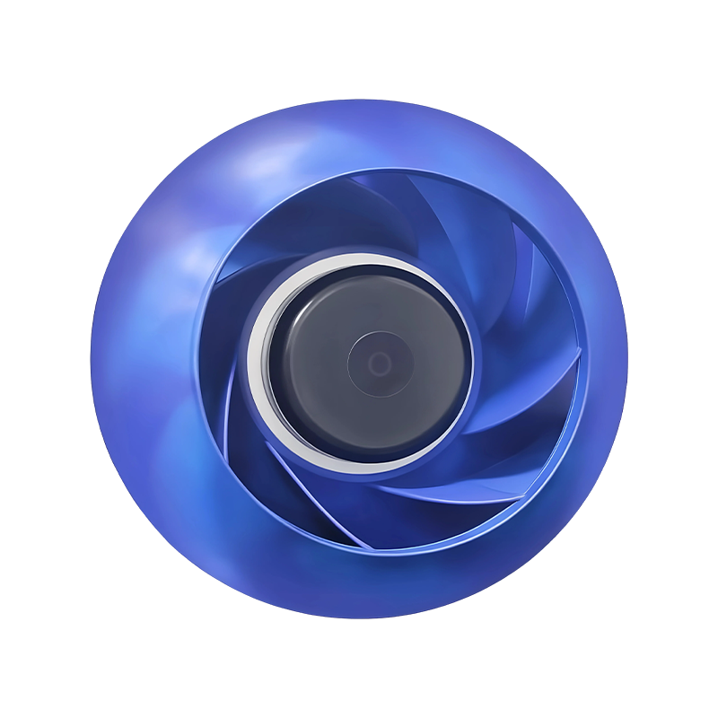
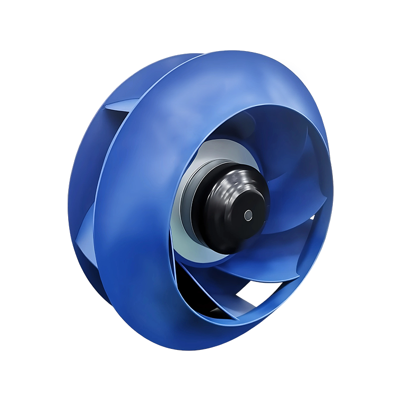
The backward-curved aerofoil impeller holds the title. Its blades are shaped like aircraft wings, with a rounded leading edge, a cambered profile, and a thin trailing edge. This geometry keeps the boundary layer attached over a wide range of flow conditions, which minimises separation losses inside the blade passage. Peak total efficiency for a well-designed aerofoil impeller regularly reaches 85 to 90 percent, and the efficiency stays high across a broad band of the flow range rather than peaking at a single point.
Indicative peak total efficiency for comparable sizes operating near their best efficiency point. Actual values vary with impeller diameter, rotational speed, gas density, and casing design.
The efficiency ranking comes with an important qualification. Aerofoil blades have a thin profile and a sharp trailing edge, which makes them vulnerable to erosion and to build-up when the gas stream carries abrasive particles or sticky material. In those conditions the theoretical efficiency advantage disappears within months, because a roughened blade surface destroys the carefully designed pressure distribution. A radial-tipped impeller with a lower nominal efficiency will often deliver a lower lifetime cost in a dust-laden duty, because it keeps its geometry far longer.
What Are the Advantages of Centrifugal Fans?
High Pressure Generation
The scroll casing converts velocity into static pressure efficiently. A single-stage machine can overcome the resistance of long duct networks, multi-stage filtration, scrubbers, and heat exchangers.
Stable Flow Under Load
Unlike a propeller fan, output does not collapse when downstream resistance rises. This makes the machine predictable in systems where filter loading changes over time.
Broad Material Choice
Impellers and casings can be produced in carbon steel, stainless grades, duplex stainless, FRP, or with ceramic and rubber linings to suit corrosive or abrasive streams.
Effective Speed Control
Because power varies with the cube of speed, reducing rotational speed by twenty percent cuts absorbed power by roughly half. Variable frequency control therefore delivers substantial energy savings.
Contaminant Handling
Open radial and radial-tipped impellers pass fibrous, stringy, and granular material without clogging, which is why they dominate sawmill, textile, and food processing extraction systems.
Discharge Direction Flexibility
The outlet can be positioned through a full range of angles by rotating the casing, allowing the machine to fit tightly into existing plant layouts without extensive re-ducting.
How to Select a Centrifugal Fan
Selection is a sequence of calculations followed by a check against the manufacturer's performance map. Skipping any step usually results in a machine that either underperforms or operates in an unstable region of its curve.
Step One: Establish the Required Volume Flow
For general ventilation, multiply the room volume by the required air changes per hour and add a margin for leakage and duct losses. A margin of ten to fifteen percent is typical. For process extraction, sum the capture volumes of each hood and apply a simultaneity factor, since not every hood operates at full demand at the same moment.
Step Two: Calculate the System Total Pressure
Total pressure has two components. Static pressure represents the resistance of ducts, fittings, filters, and process equipment. Velocity pressure represents the kinetic energy of the moving gas and is recovered at the fan outlet.
Velocity Pressure (Pa) = 0.5 × Gas Density (kg/m³) × Velocity² (m/s)
Sum the friction losses in straight duct sections, the local losses at bends, transitions, dampers, and hoods, and the pressure drop across any filters or heat exchangers. Add the discharge velocity pressure if the leaving air is not recovered.
Step Three: Determine the Absorbed Power
Shaft Power (kW) = Volume Flow (m³/h) × Total Pressure (Pa) ÷ (3,600,000 × Fan Efficiency × Drive Efficiency)
For a duty of 20,000 m³/h at 1,500 Pa with a fan efficiency of 0.78 and a belt drive efficiency of 0.95, the shaft power works out at approximately 11.2 kW. A 15 kW motor provides a sensible service factor without excessive oversizing, which would push the impeller toward the left-hand side of its curve.
Step Four: Check the Operating Point on the Fan Curve
Plot the system resistance curve against the fan's pressure-volume curve. The intersection must sit in the stable region, ideally to the right of the peak pressure point and comfortably away from the stall zone. Operation to the left of the peak causes surging, vibration, and rapid bearing failure.
Step Five: Verify Gas Conditions and Materials
Confirm temperature, humidity, dust loading, corrosiveness, and any explosive atmosphere classification. These factors determine the impeller type, the casing material, the shaft seal arrangement, and whether an explosion-proof motor and antistatic belt set are needed.
Step Six: Confirm Noise and Vibration Limits
Establish the acceptable sound pressure level at the nearest occupied position. Sound power rises roughly with the sixth power of impeller tip speed for the broadband component and with the logarithm of blade count for the tonal component. Acoustic treatment, lower speed, or a larger, slower impeller may all be required.
What Is the Correct Orientation for a Centrifugal Fan?
Orientation covers two separate decisions: the direction of rotation and the angle of the discharge outlet. Getting either wrong means the machine delivers a fraction of its rated performance, or delivers it in the wrong direction entirely.
Rotation
Viewed from the drive side of the machine, an impeller turning clockwise is designated right-hand rotation, while an impeller turning anticlockwise is designated left-hand rotation. The rotation determines which way the scroll unwinds and therefore which way the gas is thrown.
Discharge Angle
The outlet position is described by the angle between the discharge flange and a reference plane, measured in the direction of rotation. Common arrangements include the following.
| Discharge Position | Typical Reference Angle | Typical Application |
| Horizontal, same side as drive | 0° | Straight duct run along the plant wall |
| Vertical upward | 90° | Discharge into a riser or roof penetration |
| Horizontal, opposite drive | 180° | Cross-plant routing, compact machine rooms |
| Vertical downward | 270° | Discharge into a pit, hopper, or basement duct |
Many manufacturers build casings that can be rotated on site through a series of bolt positions, allowing the outlet to be repositioned without changing the impeller. If the casing is not field-rotatable, the correct orientation must be specified at the ordering stage, because reversing the rotation after delivery requires a new impeller and a new casing.
Inlet orientation also matters. A machine with a poorly arranged inlet, particularly one with a sharp bend immediately before the inlet cone, will suffer from a distorted velocity profile that reduces both pressure and efficiency and can excite vibration at the blade pass frequency. A straight run of at least three duct diameters before the inlet is a widely accepted rule.
How to Balance a Centrifugal Fan
Imbalance is the single largest cause of vibration in rotating air-moving equipment. It arises from manufacturing tolerances, from uneven material deposition on the impeller, from erosion of the blades, or from the accumulation of dust on the back plate. Balancing is therefore both a factory procedure and a recurring field maintenance task.
Static and Dynamic Balancing
Static balancing corrects the centre of gravity in a single plane and is adequate for narrow, disc-shaped impellers operating at low speed. Dynamic balancing corrects the mass distribution in two planes and is essential for wide impellers and for any machine running above roughly 1,000 revolutions per minute. Dynamic balancing also addresses the couple imbalance that static methods cannot detect.
Field Balancing Procedure Using the Two-Run Method
Prepare the Machine
Clean the impeller thoroughly, check that all blades are present and undamaged, and confirm that bearings and mountings are in good condition. Balancing a machine with a loose foundation produces meaningless readings.
Record the Baseline
Mount a vibration transducer on the bearing housing close to the impeller. Run the machine to operating speed and record the amplitude and phase of the fundamental rotational frequency. This is the original unbalance vector.
Apply a Trial Mass
Stop the machine and attach a known trial mass at a known radius on the impeller. A convenient reference mark, such as a blade edge, is used as the zero-phase reference. Run again and record the new amplitude and phase.
Calculate the Correction
Subtract the original vector from the new vector to obtain the trial mass vector. The required correction mass is the original unbalance vector divided by the trial mass vector, multiplied by the trial mass. Its angle is the reference angle plus the phase difference.
Install and Verify
Weld or bolt the calculated mass at the calculated position on the impeller. Run the machine and re-measure. Residual vibration should fall below the applicable acceptance limit. Fine trim runs may be needed to reach specification.
Three-Run Method Without Phase Measurement
When phase measurement equipment is unavailable, the three-run graphical method can be used. Three runs are performed with equal trial masses placed at three equally spaced angular positions. The resulting vibration amplitudes are plotted as radii from three points on a circle, and the intersection of the circles defines the correction mass and position. The method is slower than vector balancing but requires only a vibration amplitude meter.
Acceptance Criteria
| Application Category | Balance Quality Grade | Typical Residual Vibration |
| Small HVAC fan, resiliently mounted | G6.3 | Moderate, less critical |
| General industrial fan, rigid mounting | G2.5 | Low, standard requirement |
| High-speed process fan, precision duty | G1.0 | Very low, demanding installation |
| Laboratory or instrument cooling fan | G0.4 | Minimal, specialist applications |
Balance quality grades follow the standard ISO 1940 classification, where the number represents the permissible residual unbalance multiplied by the maximum service speed. A lower number means a tighter tolerance and a smoother-running machine.
What Is the Lifespan of a Centrifugal Fan?
Service life is not a single number, because different components wear out on completely different schedules. The impeller, the casing, the shaft, the bearings, and the drive system each have their own life profile.
| Component | Clean Air, Ambient | Dusty or Corrosive Gas | High Temperature Gas |
| Casing | 15 – 25 years | 6 – 12 years | 8 – 15 years |
| Impeller | 12 – 20 years | 3 – 8 years | 5 – 10 years |
| Shaft | 15 – 25 years | 10 – 18 years | 8 – 15 years |
| Grease-lubricated bearings | 5 – 8 years | 2 – 4 years | 1 – 3 years |
| Oil-lubricated bearings | 8 – 15 years | 4 – 8 years | 3 – 6 years |
| V-belts | 2 – 4 years | 1 – 3 years | 6 – 18 months |
| Coupling element | 4 – 8 years | 3 – 6 years | 2 – 4 years |
Bearing life is normally quoted in operating hours rather than calendar years. A well-lubricated rolling element bearing in a clean, cool, correctly aligned machine can exceed 60,000 operating hours. The same bearing in a hot, dusty environment with a misaligned belt drive may fail in 8,000 hours. Condition monitoring through periodic vibration measurement and oil analysis is the most reliable way to predict replacement before a failure causes unplanned downtime.
The impeller life is dominated by erosion and corrosion rather than fatigue, provided the machine is properly balanced. In abrasive duty, hard-facing weld overlays, ceramic tiles, or replaceable wear plates on the blade leading edges can multiply the service interval several times over.
Are Centrifugal Fans Better?
The honest answer is that they are better for some duties and worse for others. A centrifugal fan is the correct choice when the system requires meaningful static pressure, when the duct network is long or heavily loaded with filters and heat exchangers, when the gas stream carries particles that would erode a propeller blade, or when the discharge must be directed through a specific angle to fit the plant layout.
A propeller or axial fan is the correct choice when the resistance is low, the space is tight, the budget is limited, and the airflow simply needs to move from one open area to another. Mounting an axial fan in a wall is cheaper, lighter, and easier than installing a centrifugal machine with its scroll housing, base frame, and drive guard.
There is also a middle ground. Mixed-flow and tubular centrifugal designs combine some of the pressure capability of a centrifugal impeller with the inline layout of an axial fan. These are frequently used in tunnel ventilation and in retrofit projects where an existing axial duct must be upgraded without rebuilding the entire air path.
What Are the Common Problems with Centrifugal Fans?
| Symptom | Likely Cause | Corrective Action |
| Excessive vibration | Imbalance from dust build-up or blade erosion, worn bearings, loose foundation bolts, misaligned drive | Clean and rebalance the impeller, replace bearings, re-torque anchor bolts, realign pulleys or coupling |
| Bearing overheating | Insufficient or degraded lubricant, over-greasing, misalignment, excessive belt tension, ambient heat | Flush and re-lubricate to the specified quantity, check alignment, adjust belt tension, improve ventilation around the bearing housing |
| Reduced airflow | Wrong rotation, reversed impeller, blocked inlet, leaking duct, closed damper, worn impeller | Verify rotation direction, inspect and clear the inlet, seal duct joints, open dampers, measure impeller wear and replace if needed |
| Motor overload | Operating point moved to the right of the curve, gas density higher than design, mechanical binding | Reduce speed with a variable frequency drive, re-check gas temperature and density, inspect for rubbing contact |
| Surge or pulsating flow | Operating point to the left of peak pressure, system resistance higher than expected | Increase system flow, reduce resistance, install a bypass, or select a fan with a wider stable range |
| Abnormal noise | Blade pass tone, resonance with ductwork, foreign object inside casing, loose liner | Add acoustic treatment, change rotational speed slightly, remove foreign material, re-secure the liner |
| Corrosion or perforation | Condensation, aggressive gas constituents, inadequate material selection | Upgrade to a suitable stainless grade or apply an appropriate coating, improve drainage and insulation |
| Belt slippage or wear | Incorrect tension, misaligned pulleys, worn grooves, oil contamination | Re-tension, realign with a straight edge or laser, replace worn pulleys, shield belts from lubricant |
Most of these problems are predictable and preventable. A maintenance schedule built around vibration measurement, bearing temperature logging, lubricant condition, belt tension checks, and periodic impeller inspection will catch the majority of developing faults well before they cause a forced outage.
Where Are Centrifugal Fans Used?
The application list is long because the machine solves a very general problem: moving a gas against resistance.
Boiler and Furnace Duty
Forced draught fans supply combustion air, induced draught fans pull flue gas through economisers, air preheaters, and dust collectors before the stack.
Dust Collection
Bag filters, cartridge collectors, cyclones, and wet scrubbers all rely on a centrifugal fan downstream to draw contaminated air from the process.
HVAC and Cleanrooms
Air handling units, fan coil systems, and pharmaceutical cleanrooms use double-inlet centrifugal fans for their quiet operation and stable pressure delivery.
Pneumatic Conveying
Cement, fly ash, plastic pellets, flour, and grain are all transported through pipelines using the pressure generated by heavy-duty centrifugal machines.
Tunnel and Mine Ventilation
High-pressure centrifugal units supply fresh air over long distances underground and exhaust contaminated air from headings and dead ends.
Cooling Towers
Induced draught cooling towers use large centrifugal fans to draw air through the fill, handling saturated air streams without loss of performance.
Food and Agricultural Processing
Grain dryers, tea and tobacco processing lines, flour mills, and vegetable dehydration plants depend on controlled high-volume air movement.
Marine and Offshore
Engine room ventilation, cargo hold ventilation, and accommodation air handling all use marine-grade centrifugal units built to classification requirements.
Data Centre Cooling
Air handling units serving server halls use plug fans and double-inlet centrifugal fans with electronically commutated motors for precise airflow control.
Chemical and Pharmaceutical
Fume extraction, reactor headspace venting, and solvent recovery systems require corrosion-resistant centrifugal fans with gas-tight construction.
Wastewater Treatment
Aeration blowers supply air to biological treatment basins, and odour control systems extract foul air from screens and grit chambers.
Paint and Coating Plants
Spray booths require a carefully balanced extraction rate to capture overspray, which is normally provided by a radial or radial-tipped centrifugal fan.
Operating Cost and Energy Considerations
Energy consumption usually dominates the lifetime cost of a centrifugal fan installation. The fan affinity laws describe how performance changes with rotational speed, and they are the foundation of every energy-saving measure applied to these machines.
| Parameter | Relationship with Speed | Effect of a 20% Speed Reduction |
| Volume flow | Proportional to speed | Falls to 80% of original |
| Static pressure | Proportional to speed squared | Falls to 64% of original |
| Shaft power | Proportional to speed cubed | Falls to 51% of original |
| Noise level | Rises steeply with tip speed | Typically falls by 4 to 6 dB |
The cube law explains why variable frequency control is so effective. A fan that is throttled mechanically at a damper wastes the pressure it generates across the damper. A fan that is slowed electronically simply generates less pressure in the first place, and the power reduction is dramatic. Over a fifteen-year operating life, the difference in electricity cost between damper control and speed control can easily exceed the original purchase price of the machine several times over.
Selection Trade-Off: Efficiency Against First Cost
A high-efficiency aerofoil impeller costs more to manufacture than a simple forward-curved impeller of the same diameter. The decision between them should be based on annual operating hours and energy price, not on purchase price alone. A machine running 8,000 hours per year at a high load factor will repay the efficiency premium within a few years. A machine running a few hundred hours per year on a standby duty will not.
Installation and Commissioning Checks
A correct installation protects the investment. The following checks should be completed before the machine is handed over for continuous service.
Foundation and Mounting
Confirm the base is level, rigid, and capable of absorbing the machine's dynamic loads. Grout, shim, and torque all anchor bolts to the specified value. Flexible mounts must be selected for the correct load range.
Rotation Check
Bump the motor briefly and observe the impeller direction. Confirm it matches the arrow on the casing before the machine is run up to speed.
Drive Alignment
Check pulley alignment with a straight edge or laser, set belt tension by deflection measurement, and confirm the coupling gap and angular alignment on direct-coupled units.
Duct Connections
Use flexible connectors at inlet and outlet to isolate vibration. Ensure the duct does not impose load on the fan flanges, and allow adequate clearance at the inlet.
Electrical Protection
Verify motor overload settings, phase rotation, earth continuity, and the correct operation of any variable frequency drive parameters before full load running.
Baseline Vibration Record
Measure and record vibration at each bearing in all three axes at commissioning. This baseline becomes the reference for all future condition monitoring.
Materials and Construction Choices
Material selection is driven by the gas stream, not by preference. Carbon steel with an industrial coating suits clean, dry, ambient air. Stainless steel grades resist moisture and many chemical species but are vulnerable to chlorides in some conditions. Duplex stainless offers higher strength and better chloride resistance at higher cost. Fibre-reinforced plastic handles strongly corrosive fumes at moderate temperatures where metals would fail quickly. Abrasion-resistant plate, ceramic tiles, and hard-facing overlays protect impellers and casings in dust-laden duty.
The impeller is usually the most highly stressed component. It must be designed for the centrifugal forces at maximum continuous speed with an appropriate margin, and it must be balanced to a defined quality grade. Shafts are sized for the combined bending and torsional loads with a fatigue safety factor, and the first critical speed must be well separated from the operating speed and from any significant excitation frequency in the system.
Custom Engineering Inputs
Every process has its own constraints, and a standard catalogue unit does not always fit. The information that most affects a custom design includes the following.
| Design Input | Why It Matters |
| Volume flow and total pressure at the duty point | Defines impeller diameter, width, and rotational speed |
| Gas temperature and density | Sets the actual pressure capability and the material limits |
| Dust loading and particle size | Determines blade type, clearance, and wear protection |
| Chemical composition and moisture | Drives casing and impeller material selection |
| Available space and duct layout | Fixes rotation, discharge angle, and drive arrangement |
| Noise limit at a specified distance | Influences speed choice, blade count, and acoustic treatment |
| Electrical supply and control method | Determines motor rating, starting method, and speed control |
| Duty cycle and expected service life | Affects bearing selection, lubrication method, and maintenance access |
Performance Verification After Installation
A fan that performs correctly on the test stand can still underperform once installed. Field verification should measure the actual volume flow using a pitot traverse or a calibrated flow measuring station, record the static pressure at the fan inlet and outlet, and log the motor current against the nameplate value. These three measurements together confirm whether the machine is operating near its design point.
If the measured flow is significantly below the design value, the cause is usually higher than expected system resistance, an inlet obstruction, a leaking duct, or incorrect rotation. If the measured flow is above the design value and the motor current is high, the system resistance is lower than predicted, and the operating point has moved to the right of the curve. Speed reduction through a variable frequency drive is the cleanest correction in that situation.
Maintenance Schedule Framework
| Interval | Task |
| Weekly | Check for unusual noise or vibration, verify bearing temperature, inspect for dust accumulation on the casing |
| Monthly | Inspect belt tension and condition, check anchor bolts and flexible connectors, clean the inlet screen |
| Quarterly | Record vibration readings at each bearing, inspect impeller for erosion or build-up, check drive alignment |
| Annually | Replace or replenish lubricant, inspect shaft and bearing clearances, check casing thickness at wear points, verify motor insulation resistance |
| Three to five years | Full strip-down inspection, impeller rebalance, bearing replacement, casing repair or relining as required |
A documented maintenance history is valuable in its own right. Trend data on vibration amplitude, bearing temperature, and motor current will reveal a developing fault long before it becomes a breakdown, and it provides the evidence needed to justify planned replacement rather than emergency repair.
Engineering Support and Documentation
A centrifugal fan is a long-term asset, and the documentation that accompanies it should reflect that. A complete technical package normally includes the dimensional drawing, the performance curve at the specified gas density, the shaft power curve, the sound power data by octave band, the balance quality certificate, the bearing specification and lubrication schedule, the material certificates, and the installation and commissioning instructions.
For custom-engineered units, additional documentation covering the impeller stress analysis, the critical speed calculation, and any special welding or coating procedures is often required. These documents allow the maintenance team to make informed decisions years after the original installation, when the commissioning engineer is no longer available to answer questions.
Technical support during the selection phase is equally important. The most common cause of a poorly performing installation is not a manufacturing defect but a mismatch between the specified duty and the actual system resistance. Sharing the complete system layout, the gas properties, and the expected operating range allows the manufacturer to propose a machine that sits comfortably in its stable region across the full range of real operating conditions, not just at a single nominal point.
NEXT:Axial or Centrifugal Fan: Which Is Better for Your System
Interested in cooperation or have questions?
-

sale3@beron-motor.com
-
 +86-15906637529
 -
 Building 1 (12#), No. 619, Wangmei Road, Linping Street, Yuhang District, Hangzhou, China
 Wholesale Industrial Fan Manufacturers